Servo Test Stand
Before assembling the Twelve Dollar Robot Arm, I wanted to independently test the four servos. I built a servo test stand from laser-cut acrylic to hold four 9g servos during development of servo control software.
Design
I designed the servo test stand shown in Figure 1 with OnShape, a powerful 3-D computer-aided design system running as a web application. OnShape offers a free plan to hobbyists, makers, and others who are willing to freely share their designs.
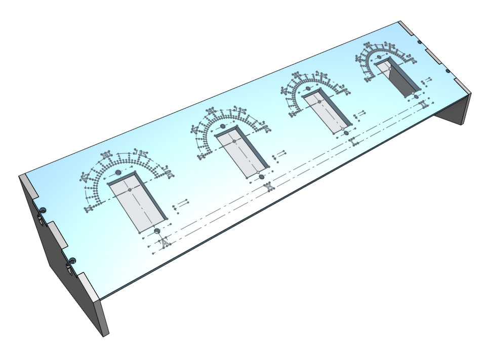
Figure 1. CAD Model of the Servo Test Stand
The OnShape CAD model shows how the acrylic parts will be cut and etched. Construction lines help locate design elements. From the Onshape CAD model
The top panel has cutouts to mount four servos side by side. This arrangement lets me simultaneously watch the position and movement of all four servos.
Above each servo, a 180° protractor is centered around the servo shaft to measure each servo horn’s rotary position. The protractors have divisions into 5° intervals, with longer marks at 15° and 45° intervals. I experimented with 1° intervals, but the laser etched markings blurred together.
The left and right sides support the top panel at a 30° angle for easier viewing. The sides interlock with the top panel using finger joints generated by Arul Suresh’s Laser Joint custom feature for OnShape. I added screw holes and T-slots to secure the sides to the top panel with M2 x 8 mm screws and nuts.
OnShape exported DXF files (Autocad’s Drawing Exchange Format) to control the laser cutter. OnShape exported separate DXF files for the faces of the left and right sides (they should be mirror images) and for the face of the top panel.
The protractor and servo labels were not cut through the faces, so OnShape omitted them from the top panel face DXF file. OnShape exported additional DXF files for the 2-D sketches of the protractor and servo labels. I used CorelDraw to combine the DXF files for the top panel, the protractor (repeated four times), and the servo labels.
RDWorks, a laser cutter control program, imported the three DXF files for the top panel and sides. Figure 2 shows the DXF patterns in the RDWorks workspace.
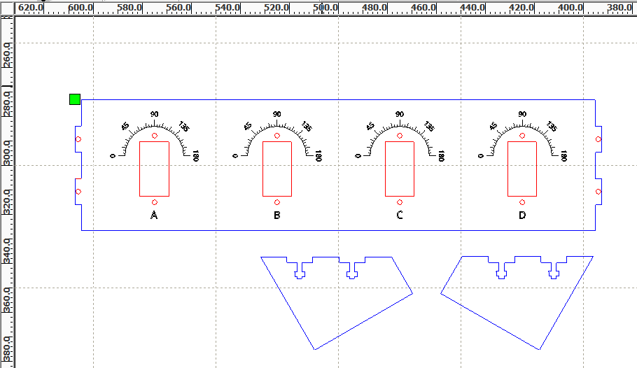
Figure 2. Laser Cutting Pattern
RDWorks’ rendering of the DXF file that controls the laser cutter. Black lines are burned at low power to etch protractors and labels. Red lines are burned next to cut holes for servos and screws. Blue lines are burned last to cut part outlines.
The three DXF files may be downloaded:
Assembly
A Hurricane 100 Watt laser cutter cut the servo test stand parts from 2.4 mm (0.093 inches) acrylic. M2 x 8 mm cap screws were inserted into the holes in the top panel’s finger joints. M2 washers and nuts were threaded onto the ends of the screws. The end support finger joints meshed with the top panel finger joints while the screw, washer, and nut assemblies slid into the T-slots. The narrow T-slots prevented the nuts from turning while the screws were tightened.
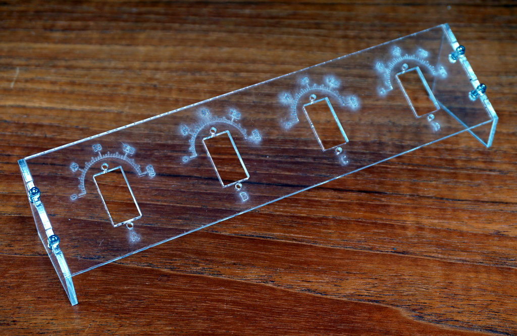
Figure 3. Servo Test Stand Assembled
M2 x 8 mm cap screws, washers, and nuts hold the servo test panel on its end supports.
The servos were mounted from the rear of the top panel. M2 x 8 mm cap screws, washers, and nuts secured the servos in place. Servo horns were pressed onto the servos with the horns pointing toward the home poistion, 90° on the protractors.
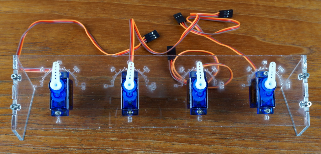
Figure 4. Servo Test Stand With Servos
The servo test stand holds four SG90 servos secured by M2 x 8 mm cap screws and nuts.
The servos were ready for calibration and software development.