Arduino Onboard Led
The Arduino Uno has an onboard LED connected to digital I/O pin 13. Arduino beginners often start by writing a program to blink the onboard LED.
Does the LED impact other uses of pin 13?
TL;DR: Not in Arduino Uno R3. Yes in the original Arduino Uno and in Arduino Uno R2.
Onboard LED Circuit
The Arduino Uno R3 schematic shows how the LED is connected to pin 13. Figure 1 consolidates and redraws the pin 13 circuitry.
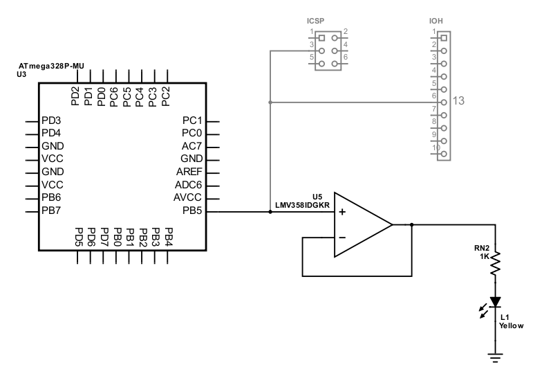
Figure 1. Arduino Uno R3 Pin 13 LED Schematic
An op-Amp voltage follower drives the on-board LED from a low-current, high-impedance input connected to Arduino pin 13. Based on Arduino Uno R3 schematic
Input/Output High (IOH) header pin 6 corresponds to Arduino digital I/O pin 13. This pin connects directly to the ATmega328P microcontroller’s port B bit 5 pin, labeled PB5 in the diagram.
PB5 also connects to the In-Circuit Serial Programming (ICSP) header pin 3. An external system sends serial clock pulses to the ATmega328P microcontroller on this line when loading a new program into flash or EEPROM memory. The ICSP header is disconnected during normal Arduino operation.
Op-Amp Buffer
The PB5 to pin 13 signal controls the LED through an LM358 operational amplifier. The op-amp output voltage rapidly rises or falls based on the difference between the positive and negative input voltages.
The op-amp’s output feeds back to its negative input in the Arduino circuit. This non-inverting op-amp configuration acts as a unity-gain buffer called a voltage follower. Electronics Tutorials offers an excellent tutorial explaining voltage followers and other operational amplifier topics.
When port B bit 5 pin changes from 0 to 1, the PB5 output voltage changes from 0 to 5 volts. The op-amp sees 5 volts on its positive input and 0 volts on its negative input. With a 5-volt difference on its inputs, the op-amp begins to raise its output voltage. As the output voltage increases, the connected negative input pin’s voltage also increases. The output voltage continues to increase until its two input pins have the same voltage, 5 volts.
Similarly, when port B bit 5 pin changes back to 0, the PB5 output voltage changes from 5 to 0 volts. The op-amp sees 0 volts on its positive input and 5 volts on its negative input, a difference of -5 volts. The op-amp lowers its output voltage (and the connected negative input voltage signal) until the output is 0 volts.
How quickly does the op-amp output change? Figure 2 shows LM358 response times of about 2 microseconds at 25°C (room temperature). Higher temperatures cause faster response times. Lower temperatures slow the response.
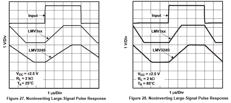
Figure 2. LM358 Op-Amp Response Times
LM358 operational amplifiers respond slower at room temperature than at higher temperatures. From the Texas Instruments LM358 datasheet
How does the op-amp help? The op-amp isolates the LED from the rest of the PB5 circuit. Op-amp inputs have a very high impedance, typically above 1 megaohms.
Ohm’s law, \( V = I \times R \), describes the relationship between voltage, current, and resistance in a conductor. Input voltage \( V \) is 5 volts. Resistance \( R \) is 1 MΩ. Solving for current \( I \) gives 5 μA.
Only 5 millionths of an amp flows from the PB5 to pin 13 signal into the op-amp. That is a tiny amount of current. The onboard LED has no impact on other uses of Arduino pin 13 as an input or output.
LED Current
The op-amp output powers the LED through a 1 KΩ current limiting resistor. The Resistor Guide explains how this part of the circuit protects the LED.
How much current flows through the LED?
The Arduino schematic and board plans loosely specify the pin 13 LED: yellow in an 0805 package. An 0805 surface mount package measures 0.08 × 0.05 inches; this is equivalent to the metric 2012 package measuring 2.0 × 1.25 mm.
A typical 0805 yellow LED is Kingbright APT2012LSYCK/J3-PRV. The datasheet shows a forward voltage drop of 1.85 volts with a forward current of 2 mA. The maximum allowable forward current is 30 mA.
This formula calculates the actual current based on Ohm’s law and Kirchhoff’s circuit laws.
$$ I = \frac{V - V_\mathit{LED}}{R} $$
Substituting the known values, the formula becomes:
$$ I = \frac{5 - 1.85}{1000} = .00315 = 3.15 \text{ mA} $$
The calculated current, 3.15 mA, is somewhat greater than the recommended current for this part, 2 mA, but well within the LED’s normal operating range. The super bright yellow LED will glow even brighter. Figure 3 shows how the forward voltage and luminance vary with current.
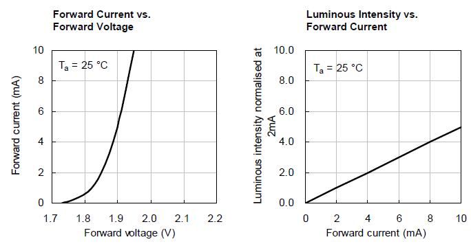
Figure 3. Yellow LED Performance
The yellow LED forward voltage drop and luminance increase as current increases. From the Kingbright APT2012LSYCK/J3-PRV datasheet
An actual Arduino Uno (or clone) board most likely contains a different, but similar LED. The onboard LED’s 3.15 mA current poses no significant drain to the Arduino board.
Earlier Arduino Uno Versions
The original Arduino Uno and Arduino Uno R2 omitted the op-amp from the onboard LED circuit. The LED and resistor connected directly to the PB5 to pin 13 signal as shown in Figure 4.
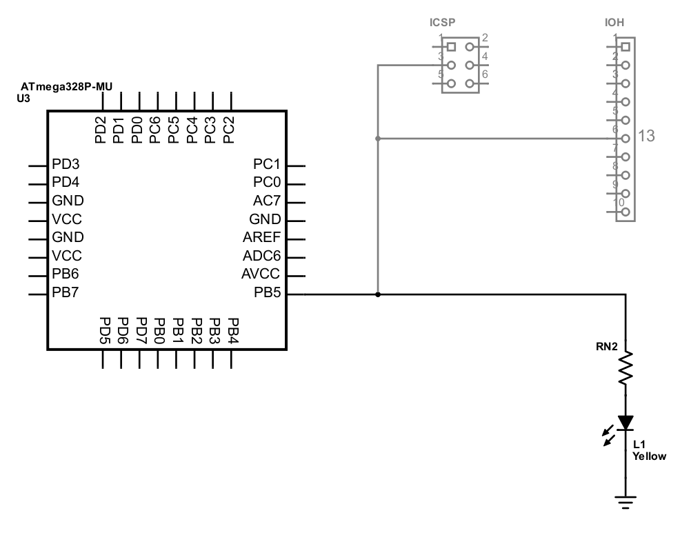
Figure 4. Early Arduino Uno Pin 13 LED Schematic
Pin 13 directly drives the onboard LED on the original and R2 Arduino Uno. Based on Arduino Uno Reference Design schematic
The original Arduino Uno used two 1 KΩ resistors in parallel for an effective resistance of 500 Ω. The later Arduino Uno R2 used a single 1 KΩ resistor. These differences may support the specific LEDs selected when the Arduino boards were designed. Starting Electronics analyzes other differences between Arduino versions.
Using the formula above, the following table shows the resulting current passing through the onboard LED.
| Version | Effective Resistance | LED Current |
|---|---|---|
| Arduino Uno | 500 Ω | 6.30 mA |
| Arduino Uno R2 | 1000 Ω | 3.15 mA |
The onboard LED may impact other uses of Arduino pin 13 on early Arduino Uno boards. The ATmega 328P microcontroller data sheet specifies a maximum current of 40 mA for I/O pins. The LED current of 3-6 mA substantially reduces the available output current and may add an unwanted input current load.
Users of other Arduino boards (Due, Mega, etc.) should check the relevant schematic to assess the impact from the onboard LED.