Laser Cutter Kerf Analysis
A laser cutter’s light beam burns narrow slots in sheet material to form parts and interior features. The width of the slot is called the kerf.
How wide is the laser cutter’s kerf?
TL;DR: About 0.22 mm.
Servo Test Stand
A servo test stand laser-cut from acrylic provided the opportunity to measure the laser cutter’s kerf. Figure 1 shows the assembled test stand with four identical rectangular holes for mounting servos.
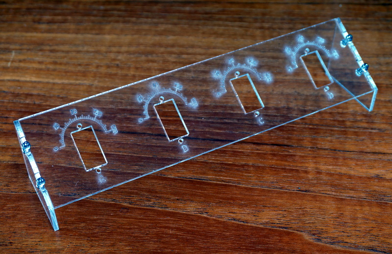
Figure 1. Servo Test Stand
This servo test stand was cut from 2.4 mm acrylic on a Hurricane 100 Watt laser cutter. From Servo Test Stand
Each rectangular hole should measure 22.5 × 11.8 mm. Figure 2 shows the the servo mounting hole dimensions from an Onshape CAD drawing. Onshape generated the DXF file that guided the laser cutter.
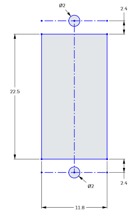
Figure 2. Servo Mounting Hole Plan
The plan calls for a 22.5 × 11.8 mm hole for the servo. Detail from the Onshape CAD drawing
The laser cutter moves its light beam along the lines shown in the CAD drawing. The machine does not understand the intention of the cuts: to make holes or to make tiles. The thickness of the light beam makes holes slightly larger and tiles slightly smaller. CAD programs can compensate for this difference once the kerf width is known.
Measurements
I measured the laser cut parts with the low-cost digital caliper from Harbor Freight shown in Figure 3. First, I measured the inside dimensions of each servo mounting hole. Next, I measured the length and width of each acrylic tile, the waste material from the inside of each hole.
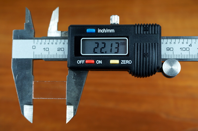
Figure 3. Measuring the Actual Size of a Cutout Tile
A digital caliper measures the length of a cutout tile from the servo test stand.
The spreadsheet in Figure 4 tabulates the measurements. The tiles were jumbled together after laser cutting, so I could not match individual tiles with corresponding holes.
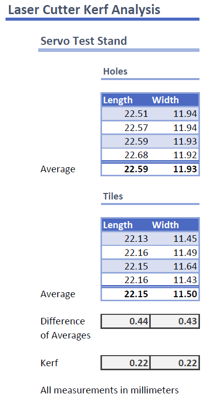
Figure 4. Analysis of Actual Hole and Cutout Tile Measurements
The laser cutter kerf is an estimated 0.22 mm based on an analysis of hole and cutout tile measurements.
The chart in Figure 5 shows the hole and tile cutout measurements. It is interesting that holes have greater variation in their length than their width while tiles have greater variation in their width. These variations may be caused by inaccuracies in the laser cutter positioning mechanism, movement of the acrylic during laser cutting, or errors in measurement from a low-cost digital caliper.
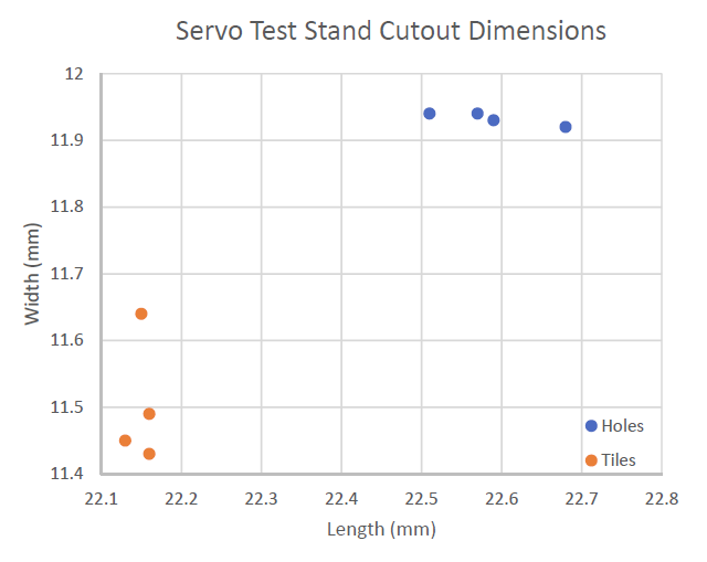
Figure 5. Hole and Cutout Tile Measurement Chart
The chart shows that holes are about 0.44 mm longer in each dimension than cutout tiles,
Analysis
The four length and width measurements were averaged for holes and tiles in the spreadsheet shown in Figure 4. Then differences were computed between average dimensions for holes and tiles.
These differences represent two kerf widths, a top and bottom kerf, or a left- and right-side kerf. The differences were divided by 2 to estimate the average kerf width of 0.22 mm.